¶ Introduction
The driver is designed to be used with retro game controllers connected to the Raspberry Pi GPIOs.
Up to 4 controllers can be used at the same time if they are of the following type:
- NES controller
- SNES controller
- PSX / PS2 controller
- N64 controller
- Gamecube controller
The driver is based on the Gamecon driver, but it uses different settings and pinouts. So there is no guarantee that it will work and you do it at your own risk!
This tutorial is not compatible with the Raspberry Pi 5.
¶ Connecting the controllers
PINS P1-01 and P1-06 are used for 3.3V power and ground. They are common to all controllers connected to GPIO. Even if the SNES / NES controllers are nominally running on 5V, they should be running on 3.3V. There is therefore NO need to use a converter on the data PINS.
The maximum current (50mA) of the Raspberry should be enough to power 4 controllers on GPIO.
However, you should use a high performance Raspberry power supply (2.1A type) to avoid any unwanted voltage drop.
The data PINS P1-03, 05, 07, 26 (GPIO0, GPIO1, GPIO4 and GPIO7) are independent of each other and each joystick uses a single PIN.
- PINS P1-03 & P1-05 correspond to GPIO2 & GPIO3 on rev.2 boards. This must be taken into account during module loading as explained in section 3.
- PINS P1-19 & P1-23 (GPIO10 & 11) are the signal PINS common to all NES / SNES controllers.
- PINS P1-08, P1-10 & P1-12 (GPIO14, 15 & 18) are the signal PINS common to all PSX / PS2 controllers.
¶ NES / SNES controllers
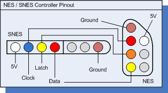
| PIN RASPBERRY | PIN SNES controller | PIN NES controller |
|---|---|---|
| P1-01 (3.3V) | 1 (power - 5V) | 1 (power - 5V) |
| GPIO10 | 2 (clock) | 5 (clock) |
| GPIO11 | 3 (latch) | 6 (latch) |
| GPIOXX | 4 (data) | 7 (data) |
| P1-06 (GND) | 7 (ground) | 4 (ground) |
¶ PINOUT NES and SNES

GPIOXX are the independent data PINs. See the driver configuration section to select the correct GPIO to use.
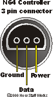
¶ N64 controllers

¶ GameCube controllers
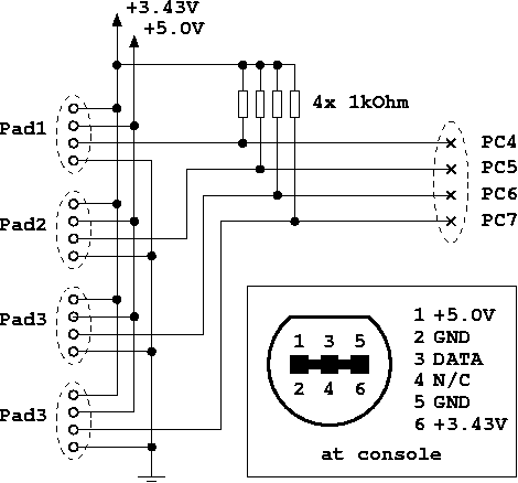
| PIN RASPBERRY | PIN GAMECUBE controller |
|---|---|
| P1-01 (3.3V) | 6 (power/3.43V) |
| GPIOXX | 3 (data) |
| P1-06 (GND) | 2&5 (gnd) |
GPIOXX are the independent data PINs. See the driver configuration section to select the correct GPIO to use.

¶ PSX / PS2 controllers
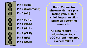
| PIN RASPBERRY | PIN controller PSX / PS2 |
|---|---|
| P1-01 (3.3V) | 5 (VCC) |
| GPIO14 | 2 (Command) |
| GPIO15 | 6 (ATT) |
| GPIO18 | 7 (CLK) |
| GPIOXX | 1 (Data) |
| P1-06 (GND) | 4 (ground) |
GPIOXX are the independent data PINs. See the driver configuration section to select the correct GPIO to use.

¶ Configure driver
¶ Configure the controllers
- Enable the Gamecon driver in the recalbox.conf file by finding the
controllers.gamecon.enabled=parameter and setting it to 1:controllers.gamecon.enabled=1. - Use the following controller index to set the parameter.
controllers.gamecon.args:map=<pad1/GPIO0>,<pad2/GPIO1>,<pad3/GPIO4>,<pad4/GPIO7>,<pad5/GPIO2>,<pad6/GPIO3>
Where <pad...> is the number defining the type of controller:
- 0 = no connection
- 1 = SNES controller
- 2 = NES controller
- 3 = Gamecube controller
- 6 = N64 controller
- 7 = PSX/PS2 controller
- 8 = PSX DDR controller
- 9 = SNES mouse
For example, if an SNES controller is connected to GPIO4 and an N64 controller to GPIO7, the mapping will be map=0,0,1,6.
- pad1 & pad2 are only used with a rev.1 card
- pad5 & pad6 are only used with a rev.2 card
- PSX/PS2 controllers require a pullup resistor. pad5 (GPIO2) and pad6 (GPIO3) have this resistor built in.
So if you have a rev.2 card, pad1 & pad2 must be set to 0.
The final controller index (used by the programs) is assigned sequentially for the connected controllers starting with 0. So, in the above example, the SNES controller would have an index of 0 and the N64 controller would have an index of 1.
- Use the following command to verify that the module has loaded successfully:
tail /var/log/kern.log
¶ Calibrate the analog axis of an N64 controller
For each N64 controller, run the following command:
jscal -s 4,1,0,0,0,6972137,6972137,1,0,0,0,6547006,6468127,1,0,0,0,536854528,536854528,1,0,0,0,536854528,536854528 /dev/input/jsX
¶ Configure response time for PSX controllers
The response time for PSX controllers is 10µs which minimizes the delay induced by the driver. However in some rare cases this is not enough to have a stable input. If you have problems when using PSX controllers, increase the delay by following the "extra modbprobe" parameter: "psx_delay=" where "delay" is the value in µs between 1 and 50.
¶ To go further
Multi-console gamepad driver for GPIO.
Thanks to marqs for the driver and for allowing us to use his "README" in the Recalbox documentation.